 |
Sponsored by INCON CORPORATION |
|
See Also:
|
Main Index > Markets > Construction Applications > Shifting Peak Energy Load Shifting Peak Energy Loads With Concrete Masonry
Construction INTRODUCTION Energy requirements for residential and commercial buildings are influenced by building design and by the materials used. Innovative designs allow peak energy demands to be shifted to off-peak hours, thus reducing costs for power generation facilities as well as consuming less energy in the building. In some communities, capacity to generate power is limited. When consumers use large amounts of power simultaneously, "brownouts" may occur. Utilities with an expanding customer base and a fixed generating capacity are faced with several options to meet their growing demand for power. The utility can expand, or build additional generating stations, requiring a substantial investment and long lead time for the station to come on-line. Another option to increase the supply of power is to buy power from another utility. This is generally more expensive than self-generated power, and may be an unreliable source, depending on the stability of the local utility grid. A third option is to use demand-side management techniques to better control the demand for power. These include conservation programs, as well as programs designed to shift some of the peak load to off-peak hours. Utilities currently promote a variety of methods to shift peak loads to off-peak periods. Perhaps the most common are programs which provide financial incentives, through the rate structure, for off-peak energy use. Some utilities will invest in their customer’s energy efficient strategies to the level of the utility’s cost savings for not having to supply that energy. Appliance cycling is another strategy which is often used to reduce peak loads. This requires the consumer’s permission for the utility to intermittently interrupt power to an appliance, usually a heat pump or electric water heater, allowing the utility to better control the distribution of power. Thermal storage is another method of shifting peak loads. Thermal storage is the temporary storage of high or low temperature energy for later use. It allows a time gap between energy use and availability. Using thermal storage, heating or cooling equipment operates during off-peak hours, and the heating or cooling energy is stored so that it is available for space conditioning during peak demand periods. Proper management of a building’s thermal storage has resulted in 10-35% reductions in peak electrical use in commercial buildings’. Much larger peak load shifts are possible with residential buildings due to the lack of significant internal heat loads from lights and other equipment, as are found in commercial buildings. Lower off-peak utility rates give the customer the benefit of reduced operating costs, since the heating, ventilating, and air-conditioning (HVAC) system runs during the off-peak hours. Energy cost savings of from 10% to 50% have been found in commercial buildings with time-of-use utility rates 1. Water, ice, and rock beds are used as thermal storage materials in some designs. Concrete masonry, however, can provide thermal storage in exterior and interior building walls with no special dedication of space or expense. These walls serve a multiple function, which may include a structural function, or a separation of living space, or an acoustical or fire separation.
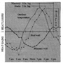
Concrete masonry is ideal for thermal storage due to its thermal mass properties. Figure 1 illustrates how the thermal mass effect causes heat transfer to be delayed and reduced through concrete masonry. The delay, illustrated in Figure 1, is representative of the load shift available with concrete masonry. Compared to lightweight materials, concrete masonry reacts more slowly to changes in temperature. This thermal lag allows concrete masonry to be "charged" with warm or cool air during off-peak hours. The masonry then slowly reacts with the interior air, to maintain a comfortable interior temperature by gaining or losing energy by convection. The reduction in the amplitude of the peaks in Figure I illustrates concrete masonry’s ability to moderate energy demand more effectively than a similarly insulated frame wall. The thermal mass inherent in concrete masonry is usually expressed in terms of heat capacity and thermal diffusivity 3. Heat capacity describes the amount of energy a wall is capable of storing. It is the product of wall weight (lb/ ft2) and specific heat (Btu/lb°F). Walls and floors with high heat capacities can store more energy, will have a larger thermal lag, and thus will generally be more effective for thermal storage and peak load shifting.
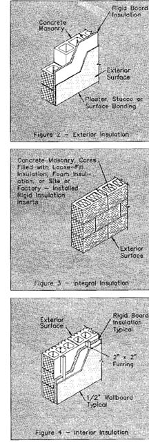
Thermal diffusivity describes the amount of heat transfer through a material relative to the amount of heat storage in the material. It is determined from the thermal conductivity (Btu.in/hr.ft2°F) divided by the product of the density (lb/ft3) and the specific heat (Btu/lb°F). Materials with low thermal diffusivities, such as concrete masonry, have a slow rate of heat transfer relative to the amount of heat storage. These materials are effective for thermal storage and peak load shifting. Thermal diffusivity and thermal mass control the thermal lag of a wall exposed to a specified temperature differential. Thermal diffusivity illustrates the important interaction between wall R-value and heat capacity - both should be large to obtain the maximum thermal lag. Insulation is most effective for this purpose when it is installed on the exterior of concrete masonry walls. This keeps the mass in direct contact with the interior air for maximum heat transfer efficiency. Exterior insulation also minimizes the effect of outdoor temperature swings on the temperature of the mass. Generally, rigid board insulation is used on the exterior of concrete masonry walls, then covered with a mesh or fabric and a weather-resistant finish, as shown in Figure 2. There are also a variety of proprietary exterior insulation and finish systems available for this use. Interior finishes on these walls should be minimal to prevent insulating the mass from the interior air. FIgure 3 shows integral insulation of a masonry wall, where there is mass on both the interior and exterior of the insulation. These walls are effective for shifting peak loads, although not as effective as exteriorinsulated walls, since the insulation isolates some of the mass from the interior. Usually, concrete masonry is insulated integrally by filling the cores with loose-fill insulation, site or factory installed rigid insulation inserts, or foamed-in-place insulation. Interior insulation, shown in Figure 4, isolates the mass from the interior air. Although this system will provide some peak reduction, it is generally not effective for shifting peak loads. Interior insulation on concrete masonry walls is usually batt or rigid board insulation between furring, covered by interior wallboard. A successful off-peak energy storage system must account for the interaction between the building envelope, thermal mass in the interior and exterior walls and floors, and the HVAC system. Proper HVAC control is crucial for effective peak load shifting. The HVAC system should be operated to allow adequate time for pre-heating (or pre-cooling) of the mass. The time will vary, depending on the number of mass elements, the required indoor air temperature, and the heat capacities of the building elements. Internal loads due to occupants, lights, and equipment also need to be taken into account, as well as climatic variables. Usually, these factors are accounted for by performing a building energy simulation, using computer programs designed specifically for this purpose.
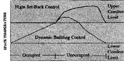
To maximize peak load shifts, a twenty-four hour temperature cycle is preferred. This allows adequate time for charging and discharging the mass with high or low temperature energy. After the mass is charged, the indoor temperature is allowed to "float" within a predetermined comfort zone. A larger comfort zone will increase the potential for peak load shifting. FIgure 5 shows a comparison of this strategy to a conventional night setback strategy for cooling. In this case, the mass is cooled to the lower limit of the comfort range, then allowed to float until the building is no longer occupied. The mass must be properly sized to reach the upper comfort limit at the end of (or after) the occupied period. A successful concrete masonry peak load shifting program has been implemented in Phoenix, Arizona4. The project was initiated by two local utilities as a result of a research effort to improve the energy performance of single family homes. Both utilities needed to reduce their peak energy loads and to shift some of the residential air-conditioning load to off-peak hours. The two utilities decided to build prototype residences, based on thermal mass computer models. The first of these prototype houses, residence "A", was designed primarily to shift the majority of heating and cooling load to offpeak hours. The house had R-15 exterior concrete masonry walls (integrally insulated block plus 2" of external insulation), internal mass walls, R30 ceiling insulation, and time of-day electric rates. The house was monitored by the utilities, and resulted in a 91-100% shift in heat pump load to off-peak hours on an annual basis. Residence "B" was designed to have a constant heat pump demand around the clock. The house had R19 walls (integrally insulated block with 2.5" of external insulation) and R30 ceiling insulation. The results from this prototype home showed that the typical load factor of the heat pump was 70-80% during the cooling season. During the heating season, a heat pump load of 61% was achieved. After the prototype evaluations, the utilities began an aggressive marketing campaign. They selected a local builder, who agreed to build one thermal mass home in the model home section of a new subdivision. The utilities also offered a financial incentive to offset any additional construction costs for the first twelve houses built in the subdivision. To interest the potential home buyers, the model house was instrumented so that temperature differences within the house were visible to potential home buyers. In this project, the advantages to be gained are twofold: the utilities benefit from the shifted peak loads, while the homeowners save considerably on their utility bills due to off-peak utility rates. The advantages of concrete masonry include reducing the amplitude of energy demand, as well as delaying the demand for energy until off-peak periods. In exterior walls, concrete masonry delays heat transfer through the exterior envelope. This time lag effect contributes to shifting demand to off peak periods. The mass of concrete masonry interior walls absorbs and stores energy, thus further contributing to shifting demand and improving thermal efficiency. Interior concrete masonry, such as acoustical partitions, stair and elevator shaft walls, and fire walls provide greater comfort by moderating temperature fluctuations through thermal mass, while at the same time providing all of the other benefits of concrete masonry.
|
|||
|
Information given herein is from sources considered
reliable, but no guarantee of accuracy can be made or liability assumed. Your
supplier may be able to provide you with more precise data. Certain compositions or
processes involving perlite may be the subject of patents. |
||||